Region mode (surface automation)
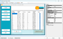
Where the Blue Prism Application Modeller cannot be used directly to identify application elements, a technique called surface automation can be used to capture an image of the application screen and map the location of key elements on it. Such applications can be modelled by using screen regions, image matching, and character recognition. This technique is useful for spying applications that are not running on the same machine as Blue Prism Enterprise, and where other spy modes are not available.
Blue Prism Region Editor is used to create reference points anchored within the parent WIN32 element, which can be defined as regions, list regions, or images. Once defined, the way in which the element is searched for at run time can also be specified. Regions defined as images can be searched for anywhere within the target application, within a defined area (with optional search padding), or by a location relative to its parent element.
Start spying with Region mode (Application Modeller)
- If the application you want to spy is not already open, in Application Modeller, click Launch.
- Click Identify.
- Press Alt to tab through the available spy modes until the required mode displays.
- Hover the mouse cursor over the application, hold Ctrl, and click the left mouse button.
The application opens, and Launch changes to Identify.
The spy mode selection dialog (identification tool) displays.
Blue Prism Region Editor opens.
Open region in existing screenshot
To open Blue Prism Region Editor from Application Modeller, to view and edit a region that has been previously spied using Region mode:
- In Application Modeller, select an element in the tree view that has been spied using Region mode.
- Click the drop-down arrow next to Regions.
- Click View overlaid on existing screenshot.
Blue Prism Region Editor opens displaying the region overlaying the existing screenshot. You can edit the region, and, if required, you can add more regions to the screenshot, to apply to the parent element.
Open region in a new screenshot
If the element within a region is not static, such a button that contains text that changes when the button is clicked, you may need to take a new screenshot to collect the alternative text on the button. To view the region overlaying a new screenshot:
- In Application Modeller, select an element in the tree view that has been spied using Region mode.
- Click the drop-down arrow next to Regions.
- Select View overlaid on new screenshot.
- Hold Ctrl and click the highlighted application to take a new screenshot.
The Identification tool displays, in Bitmap mode. You cannot change the spymode.
Blue Prism Region Editor opens displaying the region overlaying the new screenshot. You can now collect new attribute information from the region and apply it to the model.
Create region
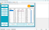
- In Blue Prism Region Editor, click Region, and drag the cross-hatched box around the area you want to capture.
- Click OK.
- Select the element in the element tree, and expand the element to see all child regions.
- Select the element and click Highlight element to check that the element is correctly identified.
- Select each child region and click Highlight element to check that each region is correctly identified.
- If required, click Open Editor to continue defining or editing regions. Click Select to move or resize regions.
- When you are ready, click Apply changes in the Element attributes tab to apply the region data to the application model.
You can zoom in or out of an area of the image before selecting it as a region.
The cross-hatched box changes to green, and the information panel is automatically populated with information specific to the selected region. For more information about each of the properties and the information they contain, see Define a region.
Application Modeller displays.
Create list region
A list region is a series of adjoining cells of the same size. List regions can be used to create a region from columns in a grid or table to be read by a Read stage and stored in a collection.
- In Blue Prism Region Editor, click List region, and drag the top cell around the top list item or cell you want to capture. Drag to resize the cells to make sure that the list region accurately fits around the cells you want to capture.
- Click OK.
- Select the element in the element tree, and expand the element to see all child regions.
- Select the element and click Highlight element to check that the element is correctly identified.
- Select each child list region and click Highlight element to check that each list region is correctly identified.
- If required, click Open Editor to continue defining or editing list regions. Click Select to move or resize regions.
- When you are ready, click Apply changes in the Element attributes tab to apply the region data to the application model.
You can zoom in or out of an area of the image before selecting it as a list region.
The list region becomes green, and the information panel is automatically populated with information specific to the selected list region. For more information about each of the properties and the information they contain, see Define a region.
Application Modeller displays.
Define region
Once you have created a region, a panel displays with a number of configurable options that allow you to specify how the element is searched for at run time.
|
Setting |
Description |
|---|---|
|
Region |
Select a region from the drop-down list. Only visible regions are available for selection. |
| Visible |
Select True to display the selected region, or False to hide it in Blue Prism Region Editor. |
| Font |
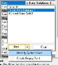
Select a font from the drop-down list to be used for character recognition. You can also click New to generate a new font or click Clear to clear the selection. For more information, see Identify a system font. |
| Retain Image |
This option cannot be changed. The image from the spied region is retained in the current region. |
| Name |
If required, enter text to rename the region. |
| Location Method |
Select the method from the drop-down list that will be used to locate a region at run time.
|
| Position |
Select Fixed to limit the search for the stored image at run time to the image location originally recorded when modeling the application, and the defined padding around it. Select Relative to search for the region at run time in a location relative to its parent element. Select Anywhere to search the all of the region's parent element at run time. This is only available if the Location Method is set to Image. |
| Colour Tolerance |
Specify the tolerance level when comparing the RGB components at run time. Valid values are 0 to 255. |
| Grayscale |
Select True from the drop-down list to use grayscale in the image to search for the region. Select False from the drop-down list to not use grayscale in the image to search for the region. |
|
Region Rectangle (X, Y, Width, Height) |
Specify the coordinates of the region in millimeters. |
|
Search Padding (All, Top, Left, Right, Bottom) |
Specify the padding around the region, in millimeters, to be searched for when the position has been set to Fixed. |
Identify system font
Blue Prism Region Editor allows you to search for fonts on your machine that match the text in a selected region, and generate them for use with character recognition.
Native character recognition based on font matching is leveraged through the Recognise Text action in a Read stage when used against a previously captured Application Modeller region. This extracts text data from the region and stores it in a Data item. The input parameters for the Recognise Text action are font, foreground color, and background color.
For more details, see Fonts and Optical character recognition (OCR).
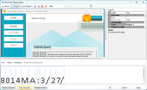
- Select a region containing text and click Show characters.
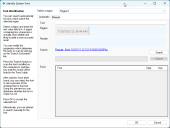
- Open the Font drop-down list in the information panel and click New, then Identify System Font.
- Make sure the correct region is selected in the Region drop-down list.
- Enter the characters displayed inside the selected region that you want to be included in the font matching search in Text.
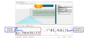
The characters are displayed in the character preview panel with the selected font name and number of characters defined for that font displayed above it. If no font has been defined, this information will be blank. If a font has been defined (by selecting a font from the Font drop-down list in the information panel), you can click Show All Characters to display punctuation and symbols, or leave it unselected to only display alphanumeric characters.
The Identify System Font window displays.
Automatically search
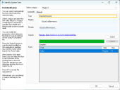
- If you want to search for the text automatically, click the Automatic tab.
- Click the Search link.
- Deselect any parameters that you do not want to be included in the automatic search and Click OK.
- In the Identify System Font dialog, click Search.
-
Click each result to see a preview in the Render field.
- Select the closest match and click OK.
The search criteria displays as a link.
The longer the search criteria, the longer it takes for the automatic search to complete.
The Search parameters dialog displays.
Possible matches display in the Fonts area.
Manually search
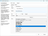
- Click the Manual tab.
- Estimate the font size and style, and select them from the Sizeand Style drop-down lists.
- Click Render List.
- If the result in the Render field is not close enough to the original text, select a new font from the Font area, and adjust the size and style until you get a close match.
- Click OK.
A preview displays in the Render field.
Generate a font
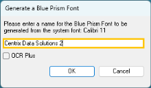
After you either automatically or manually identify a font, and click OK, the Generate a Blue Prism Font dialog displays.
- Enter a name for your new font and click OK.
- If required, select the OCR Plus option. This improves the robustness of the font matching algorithm and color identification. For more details, see OCR Plus
- In Region Editor, Click Apply and OK.
To use Optical character recognition (OCR) with a font, you must first disable the Smooth edges of screen fonts setting in Windows Settings > Performance Options > Visual Effects.
This
You are returned to Region Editor. The font name and number of characters are updated, and the new font is also available for selection in the Font drop-down list for all regions.
You are returned to Application Modeller. The new font is added to the Attributes list for the region. The font is also added to the System – Fonts screen in the System tab where it can be edited, exported and more. For more information, see Fonts .
Create empty font
- Select a region, open the Font drop-down list in the region information panel and click New, then Create Empty Font.
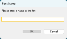
- Enter a font name, and click OK.
The Font name dialog displays.
The font name is now displayed above the character pane, and the font is available for selection in the Font drop-down list for all regions. The font is also added to the System – Fonts screen in the System tab where it can be edited, exported and more. See Fonts .
Merge characters into font
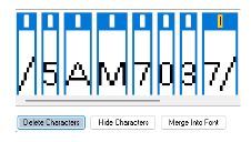
You can extract specific characters from the selected region, identify them, and merge them into the selected font.
- Select a region, then select a font for the region from the Font drop-down list.
- Click Show characters.
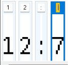
- Identify and confirm each character by typing the character into the top of each of the extracted characters' text fields.
- Click Merge Into Font.
- Select any unmerged characters that you want to delete by pressing Ctrl and clicking the left mouse button on any character you want to select.
- Click Delete Characters.
The extracted characters display in the bottom panel.
To hide the character pane at any time, click Hide characters.
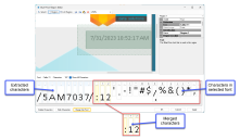
Any characters that you identified and confirmed in step 3 are merged into the selected font, and will be included when character recognition is utilized. The new characters are highlighted yellow. Any undefined extracted characters remain in the panel but are not merged into the font.
The total number of characters displayed above the panel is also updated.
Delete characters
You may want to clear the character pane of any characters that you do not want to merge into the font.
Selected characters are highlighted blue.
The selected characters are deleted.
 Docs
Docs